Monitoring device for automatic production of barrel stamping (1)
Text / Jia Qianzhen
In the production of steel drums, many parts are stamped, such as the bottom of the barrel, the top of the barrel, the closure, the lifting ring, the lifting ring seat and so on. In the high-productivity automatic production process of steel drum parts, the operator only looks at the production process, and discovers and handles accidents and wastes, which is a great burden both mentally and physically. It is a scientific method to use various monitoring and detecting devices instead of operators to monitor the relevant links of stamping to achieve automatic protection during the production process and to ensure orderly and stable normal production.
Figure 1 shows the detection devices with various monitoring functions in all aspects of stamping automatic production. Their functions and applications are briefly described as follows:
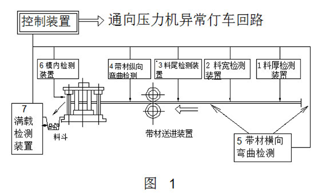
1, material thickness detection
This test is not used in general, but it is necessary to use it when the material thickness error is large or when precision parts are punched.
2, material width detection
In the case of small, no-waste stamping, when the original width strip material is used, width detection is required. When multi-station die stamping is used, side edge trimming is often used for feeding. At this time, the lateral bending (snake) detection of the strip is more advantageous than the strip width detection.
3, tail detection
It is important to display the strip as it reaches the end and immediately stop the press. It tells the operator to add new material for easy machine management.
4, strip longitudinal bending detection
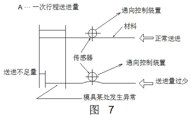
When a station mold fails, the next blank cannot be fed. In this case, if the strip feed is hindered, longitudinal bending will occur. Therefore, longitudinal bending is the most typical defect exposed to the surface of the strip due to a mold accident.
5, strip transverse bending detection
When the thickness of the stamping material is large, if the strip is unable to pass due to severe lateral bending, many scraps will appear, and not only that, but it will also be the cause of mold damage.
6, in-mold detection
This test is not only required for mold protection, but also for the accuracy and quality of the part.
7, finished product storage hopper full load detection
This is done by using a hopper or arranging parts. If this part is not tested, the system will overflow the hopper and cause unnecessary accidents.
The sensing method of the detecting device is of contact type and non-contact type. The former mainly operates the electrical contacts by mechanical means, and the latter obtains signals by electromagnetic induction, photoelectric or beta rays.
There are two types of signals: one is to determine whether there is a fault directly from the signal of the detection device (on or off); the other type of signal must be related to the specific position or time of the stamping work cycle to determine whether there is a fault. Once the fault occurs, the signal leads to the abnormal stop circuit of the press.
The typical structure and principle of operation of various monitoring and detection devices are briefly described below.
First, electromechanical detection device
1, material thickness detection
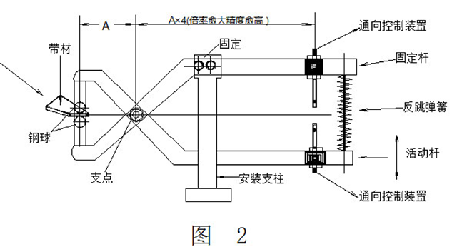
For parts with strict tolerance requirements, the material thickness detection is more complicated. In the case where a formal inspection is required, diamond needle contact detection can be used.
The plywood material thickness detection method shown in Fig. 2 has practical value on site. The electric measuring portion and the gripping material portion form a large lever ratio centering on the fulcrum, so that a relatively accurate detection can be performed. In the figure, when the end steel balls of the gripping material pass through the thin material, the contact terminals come into contact and the input signal is sent to the control device. If the contact terminal is adjusted in advance in this state, an output signal is sent to the control device when the thick material passes.
2, material width detection
This detection method is not complicated. Fig. 3 is an example of the detecting device. As shown in the figure, when the end portion of the L-shaped bar with the roller moves left and right, it comes into contact with the A or B limit switch, thereby turning on the control circuit.
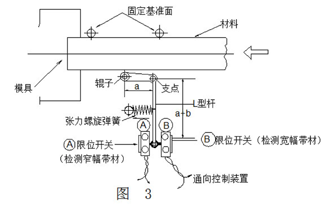
The detection method can also use the lever ratio to amplify the actual minute size. The limit switch can be fine-tuned to adjust the limit switch by placing a basic gauge sheet between the maximum width and the minimum allowable tolerance between the reference surface and the roller.
When the strip size is wide, the B limit switch is turned on, and the width is too small. Under the action of the tension coil spring mounted on the arm, the A limit switch is turned on, and an input signal is sent to the control device to stop the press.
3, tail detection
Generally, the detection device provided by the automatic press shown in FIG. 4 is used for detecting more, but when using a pneumatic feeder or a feeder (ie, a pull feeder) behind the press, it is necessary to consider setting as shown in the figure. 5 special tail detection device. A constant limit switch is provided on the side of the lever with the fulcrum, and a rod or roller is provided on the other side. In order to allow the belt to be tensioned by the rollers when passing, the fixing bracket should be moved to the inlet for installation. When the strip reaches the end, the lever is in a free state due to the loss of tension, at which point the input signal is sent to the control unit.
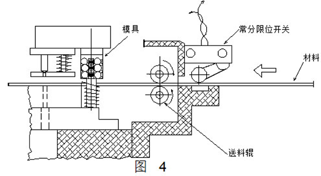
It is better to use a constant limit switch on the tail end detecting device. The reason is that if the control switch is charged normally, and once an abnormal situation occurs (refers to the end of the strip), it is only necessary to give the input signal of the cut-off circuit, so as to avoid accidents such as loop disconnection and switch misoperation. . The press is not allowed to operate without a detection and protection circuit, which is the most reliable method.
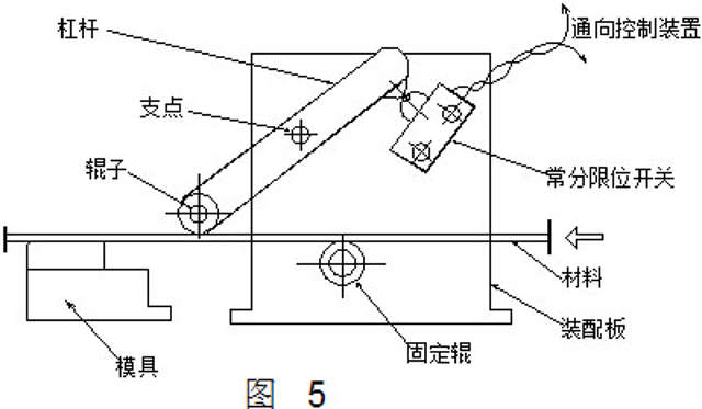
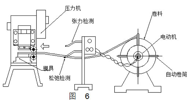
Figure 6 is an automatic reel. This is configured for feeding the strip and the unit automatically feeds the material at the processing speed of the press. The reel is equipped with an electric motor, which is the principle that the strip is slackened when too much strip is fed at the detecting device.
When the slack strip comes into contact with the underlying rod, the motor switch of the reel is disconnected and the motor stops rotating. However, after a period of time, the strip is brought into tension to contact the upper rod, so that the motor is turned on, and at this time, the reel is rotated, the strip is fed, and the process is repeated.
4, strip longitudinal bending detection
As mentioned earlier, the longitudinal bending of the strip is the most obvious exposure of the various anomalies occurring within the mold and, therefore, is more important than other tests.
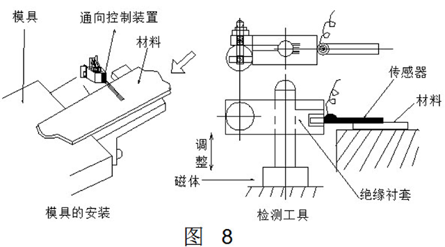
Figure 7 shows the longitudinal bending of the strip, and Figure 8 shows the measures taken. The device is simple, but it is important to set the device to the best effect and the most easy to arch in the event of an abnormality. This requires careful observation of the mold.
Needless to say, in each short-distance feeding or stamping of thick strips, the longitudinal bending is often not significant, and further research is needed on how to obtain the corresponding accuracy. In addition, since the tape is originally somewhat curved, there is a case where the tape is in contact with the contact terminal and the press is stopped. Therefore, it is preferred to use a guide at the inspection device to keep the strip as flat as possible.
5, strip transverse bending detection
To save raw materials, shape detection is an indispensable item. Generally, by sequential feeding, the edge of the strip (side edge trimming) can be cut off in the multi-station mold to achieve the purpose of correction. However, in the case of severe lateral bending, it is inevitable to damage expensive molds.
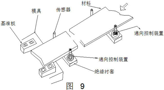
Figure 9 shows an example of the shape detection. This example is only applicable to strip materials that are conductor materials and not suitable for non-conductor materials. It should be noted that it is advisable to place the sensor for detection at a distance from the mold.
6, in-mold detection
In-mold testing includes whether the material is fed or the workpiece is positioned accurately; whether the punch is broken; whether the top device is working properly; whether the output is smooth, etc. There are many forms of such detecting devices, and several typical examples are introduced here.
(1) Positioning detection method
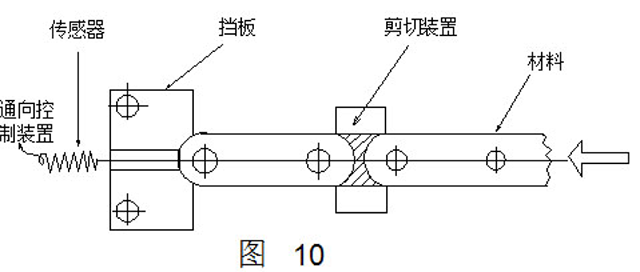
When the positioning process of Fig. 10 is employed, the sensor is disposed in the positioning portion so that the press slider is punched down only when the material is fed to the top position and contacts the sensor. Once the advancement distance is insufficient, the material does not touch the sensor and the slider cannot be lowered.
(2) Automatic gear detection method
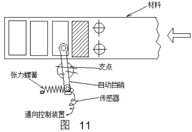
This detection method uses the principle that the lever moves left and right around the pivot point (see Figure 11). When the strip is top-to-head, under the action of the automatic stop pin, the strip touches the sensor each time. When it is not touched, the strip can be considered to have not been fed, and the press can not work.
(3) Conductive pin detection method
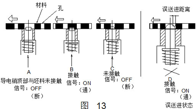
The detection method uses the waste hole to detect whether the feeding is accurate each time, and the detecting device is disposed in the lower mold (see Fig. 12). The conductive pin is insulated by the insulating sleeve, and the top end of the pin is slightly smaller than the scrap hole. When the strip passes over, the conductive pin instantaneously contacts the strip and the line is turned on, but when the conductive pin pushes out the next hole, the line is cut off, and each line is cut off. The duty cycle in turn cyclically sends an input signal to the control device that is turned on and off.
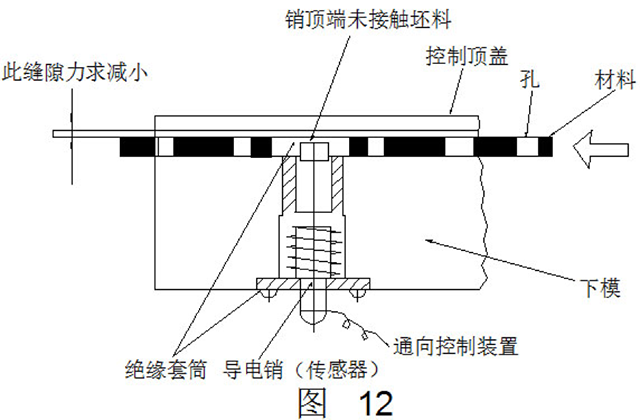
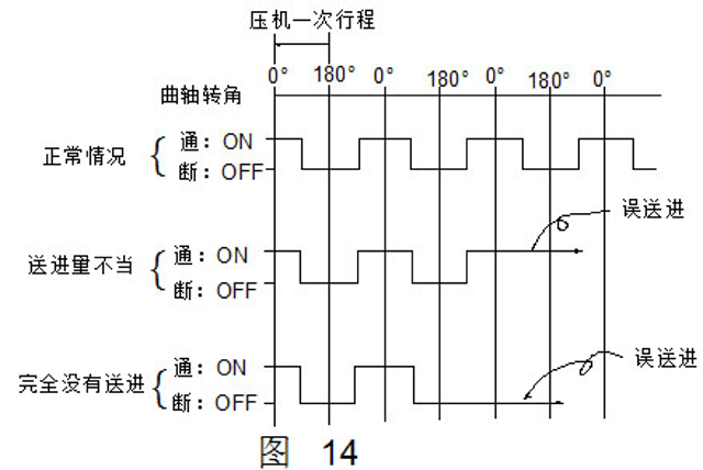
Figure 13 shows a duty cycle diagram. When the misfeed is issued, the conductive pin does not eject as shown in the figure D. Since the conductive pin remains in contact with the strip, the line is in the on state. Fig. 14 is a diagram showing the input signal of the conductive pin detection in the normal case and the misfeed. When the feed amount is improper or not fed at all, the detecting device can operate the press slider to stop working.
In order to enable the conductive pin to smoothly enter and exit the strip waste hole, the straight side portion of the pin should not be higher than the upper plane of the concave mold, so the detection accuracy of the method is affected by this. To further improve the detection accuracy, the method shown in FIG. 15 can be used. High precision rod detection method. In this method, the conductive pin does not move according to the strip, but automatically moves each time through the air passage opening and closing signal from the timing cam mounted on the press. Therefore, the straight portion of the conductive pin of the method does not hinder even if it enters the hole of the strip waste. Since the pin diameter and the waste aperture are close to each other, the error of the pitch feed can be detected with high precision.
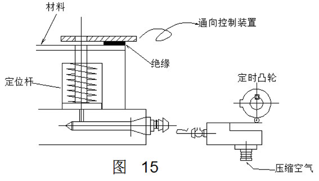
This method is not so much a simple feed error detection, but rather has the function of checking the quality of the part.
ã€Related Links】
Monitoring device for automatic production of barrel stamping (1)
Monitoring device for automatic production of barrel stamping (2)
Stainless Steel Small Steamer,Metal Vegetable Steamer,Stainless Steel Vegetable Steamer,Steel Steamer
Jiangmen Junerte Stainless Steel Kitchenware Co.,Ltd , https://www.jetkitchenware.com
